Retransmissions and duplicate ACKs are reactive TCP functions designed to recover from packet loss. TCP would be a poor protocol if it didn’t include some form of proactive method for preventing packet loss, but luckily it does.
TCP implements a sliding-window mechanism to detect when packet loss may occur and adjust the rate of data transmission to prevent this. The slidingwindow mechanism leverages the data recipient’s receive window to control
the flow of data.
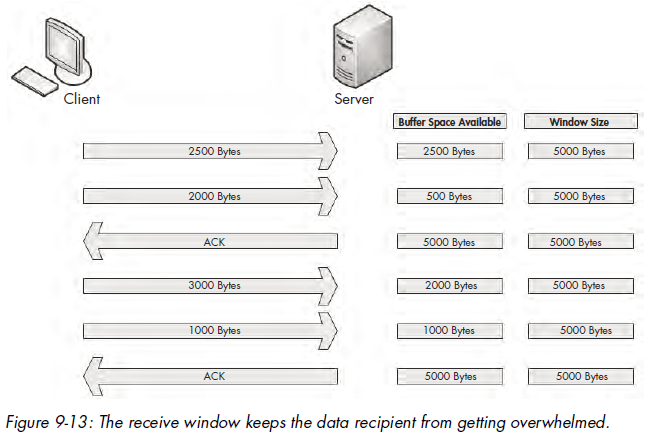
The receive window is a value specified by the data recipient and stored in the TCP header (in bytes) that tells the transmitting device how much data it is willing to store in its TCP buffer space. This buffer space is where data is stored temporarily until it can be passed up the stack to the application layer protocol waiting to process it. As a result, the transmitting host can send only the amount of data specified in the Window Size field at one time. In order for the transmitter to send more data, the recipient must send an acknowledgment that the previous data was received. It also must clear TCP buffer space by processing the data that is occupying that position. Figure 9-13 illustrates how the receive window works.
In Figure 9-13, the client is sending data to a server that has communicated a receive window size of 5,000 bytes. The client sends 2,500 bytes, reducing the server’s buffer space to 2,500 bytes, and then sends another 2,000 bytes, further reducing the buffer to 500 bytes. The server then sends an acknowledgment of this data. It processes the data in its buffer and then has an empty buffer available. This process repeats, with the client sending 3,000 bytes and another 1,000 bytes, reducing the server’s buffer to 1,000 bytes. The client once more acknowledges this data and processes the contents of its buffer.
Adjusting the Window Size
This process of adjusting the window size is fairly clear-cut, but it isn’t always perfect. Whenever data is received by the TCP stack, an acknowledgment is generated and sent in reply, but the data placed in the recipient’s buffer is not always processed immediately.
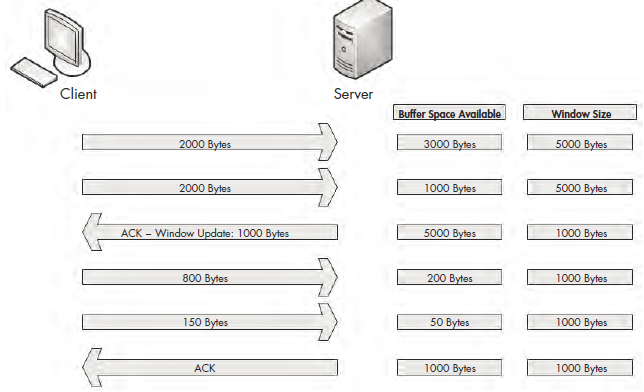
When a busy server is processing packets from multiple clients, it’s quite possible that the server could be slow in clearing its buffer and not be able to make room for new data to be received. With no means of flow control, this could lead to packets being lost and corruption of data. Fortunately, when a server becomes too busy to process data at the rate its receive window is advertising, it can adjust the size of the receive window. It does this by decreasing the window size value in the TCP header of the ACK packet it is sending back to the hosts that are sending it data. Figure 9-14 shows an example of this.
Figure 9-14: The window size can be adjusted when the server becomes busy.
In Figure 9-14, the server starts with an advertised window size of 5,000 bytes. The client sends 2,000 bytes, followed by another 2,000 bytes, leaving only 1,000 bytes of buffer space available. The server realizes that its buffer is filling
up quickly. It knows that if data transfer keeps up at this rate, packets will soon be lost. To rectify this, the server sends an acknowledgment to the client with an updated window size of 1,000 bytes. As a result, less data is sent by the client, and the server can process its buffer contents at an acceptable rate that allows data to flow in a constant manner.
The resizing process works both ways. When the server can process data at a faster rate, it can send an ACK packet with a larger window size.
Halting Data Flow with a Zero Window Notification
In some cases, a server can no longer process data sent from a client. This might be due to a lack of memory, lack of processing capability, or another problem. This could result in packets being dropped and the communication process halting, but the receive window can help minimize the negative impact.
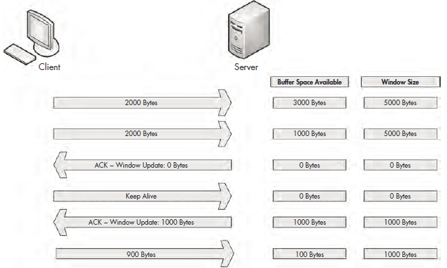
When this situation arises, a server can send a packet that contains a window size of zero. When the client receives this packet, it will halt any data transmission but will keep the connection to the server open with the transmission of keep-alive packets. Keep-alive packets are sent by the client at regular intervals to check the status of the server’s receive window. Once the server can begin processing data again, it will respond with a nonzero window size, and communication will resume. Figure 9-15 illustrates an example of zero window notification.
Figure 9-15: Data transfer stops when the window size is set to 0 bytes.
In Figure 9-15, the server begins receiving data with a 5,000-byte window size. After receiving 4,000 bytes of data from the client, the server begins experiencing a very heavy processor load, and can no longer process any data from the client. The server then sends a packet with the Window Size field set to 0. The client halts transmission of data and sends a keep-alive packet. After the keep-alive packet, the server responds with a packet notifying the client that it can now receive data, and that its window size is 1,000 bytes. The client resumes sending data.
The TCP Sliding Window in Practice
Having covered the theory behind the TCP sliding window, we will now examine it in the capture file tcp_zerowindowrecovery.pcap.
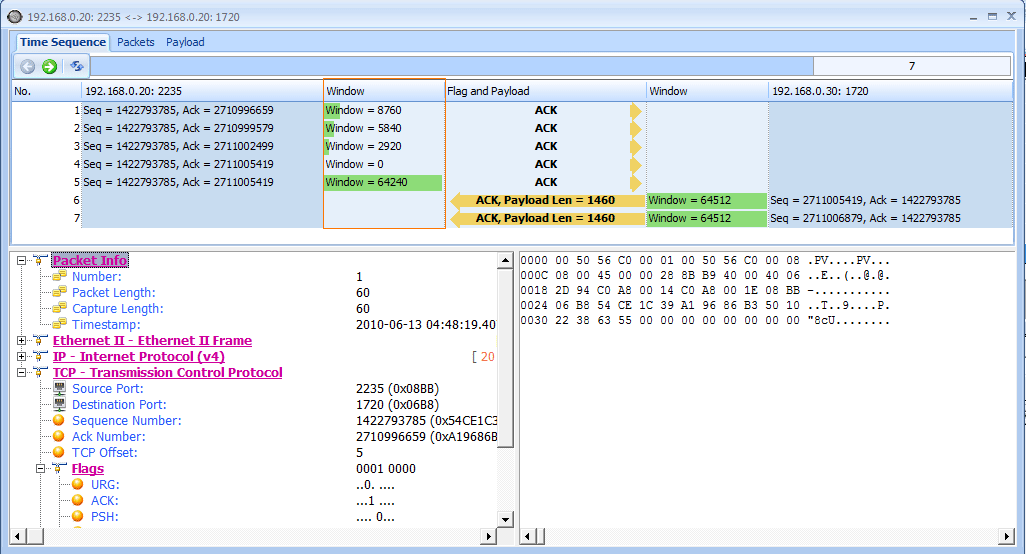
In this file, we begin with several TCP ACK packets traveling from 192.168.0.20 to 192.168.0.30. The main value of interest to us is the Window Size field, which can be seen in both the Info column of the Packet List pane and in the TCP header in the Packet Details pane. You can see immediately that this field’s value decreases over the course of the first three packets, as shown in Figure 9-16.
Figure 9-16: The window size of these packets is decrementing.
This value goes from 8,760 bytes in the first packet to 5,840 bytes in the second packet and then 2,920 bytes in the third packet . This lowering of the window size value is a classic indicator of increased latency from the host. Notice in the Time column that this happens very quickly . When the window size is lowered this fast, it’s common for the window size to drop to zero, which is exactly what happens in the fourth packet, as shown in Figure 9-16.
This value goes from 8,760 bytes in the first packet to 5,840 bytes in the second packet and then 2,920 bytes in the third packet . This lowering of the window size value is a classic indicator of increased latency from the host. Notice in the Time column that this happens very quickly . When the window size is lowered this fast, it’s common for the window size to drop to zero, which is exactly what happens in the fourth packet, as shown in Figure 9-16.
The fourth packet is also being sent from 192.168.0.20 to 192.168.0.30, but its purpose is to tell 192.168.0.30 that it can no longer receive any data. The 0 value is seen in the TCP header.
Once this zero window packet is sent, the device at 192.168.0.30 will notsend any more data until it receives a window update from 192.168.0.20 notifying it that the window size has increased. Luckily for us, the issue causing the zero window condition in this capture file was only temporary. So, a window update is sent in the next packet, as shown in Figure 9-16.In this case, the window size is increased to a very healthy 64,240 bytes .
Once the update packet is received, the host at 192.168.0.30 can begin sending data again, as it does in packets 6 and 7. This process takes place very quickly. Had it lasted only slightly longer, it could have caused a potential hiccup on the network, resulting in a slower or failed data transfer.
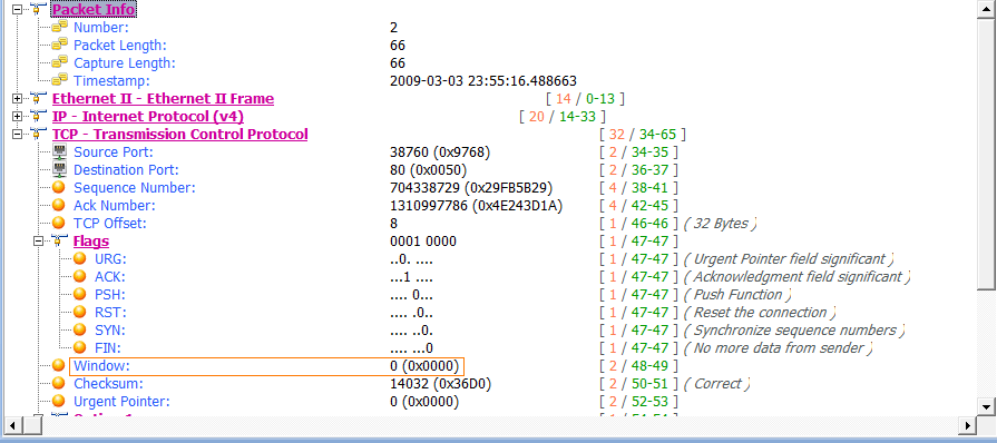
As one last look at the sliding window, examine the file tcp_zerowindowdead.pcap. The first packet in this capture is normal HTTP traffic being sent from 195.81.202.68 to 172.31.136.85. The packet is immediately followed with a zero window packet sent back from 172.31.136.85, as shown in Figure 9-19.
Figure 9-19: Zero window packet halting data transfer
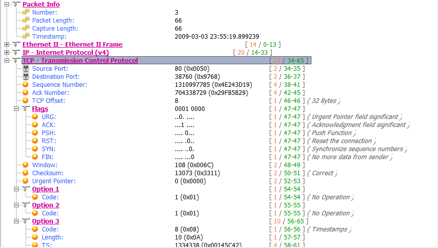
This looks very similar to the zero window packet shown in Figure 9-16, but the result is much different. Rather than the 172.31.136.85 host sending a window update and communication resuming, we see a keep-alive packet, as shown in Figure 9-20.
Figure 9-20: This keep-alive packet ensures the zero window host is still alive.
The Delta Time column tells us that this packet occurred 3.4 seconds after the last received packet. This process continues several more times, with one host sending a zero window packet and the other sending a keep-alive packet, as shown in Figure 9-21.
These keep-alive packets occur at intervals of 3.4, 6.8, and 13.5 seconds . This process can go on for quite a long time, depending on the operating systems of the communicating devices. In this case, as you can see by adding up
the values in the Time column, the connection is halted for nearly 25 seconds. Imagine attempting to authenticate with a domain controller or download a file from the Internet while experiencing a 25-second delay—unacceptable!


